ToUcam 740 Pro ICX-098BL B/W Mod (1)
First of all
Don't listen to friends and family asking why you risk that nice little
camera that's already taking sooo nice pictures just to loose it's colors
![]()
Preface
I had my key experience trying to image Venus' cloud structures with an UV-pass filter and my ToUcam Pro. Several attempts with different f-ratios from f/36 to f/12 showed that the standard ToUcam is not responsible enough in the near UV-band around 365nm to get decent results while other Venus observers reveice very good images with an commercial Atik ATK-1HS II cam which is basically a webcam with a Sony ICX-098BL B/W CCD sensor, long exposure capabilities and active cooling. Fortunately the ICX-098BL CCD is the pin-compatible black&white counterpart of the ICX-098BQ used in the ToUcam Pro so it's possible to replace the color CCD of a ToUcam pro with it's black&white brother. The 098BL is told to be about 3 times more sensible than the 098BQ due to the lack of RGB filters and the spectral sensitivity curves of the datasheets show it's higher sensitivity in the near UV band:
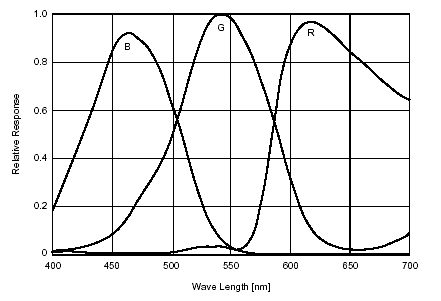
Spectral sensitivity curve Sony ICX-098BQ
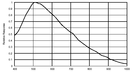
Spectral sensitivity curve Sony ICX-098BL
Beneath imaging Venus with an UV-pass filter other applications are conceivable for a more sensitive B/W cam:
- LRGB planetary imaging: The L (lightness) channel can be recorded with the more sensitive B/W cam while RGB color information is collected with a standard ToUcam. The more sensitive B/W cam allows lower gain settings (less noise) and shorter exposure times (better "freezing" of seeing).
- LRGB imaging with IR L channel: Some objects like Mars show more surface details in the near IR-spectrum. Using IR-pass filters cost quite an amount of light. Having a more sensitive cam for the L channel is a good thing.
- B/W planetary imaging: Imaging the moon or sunspots doesn't require color. B/W imaging of planets with a more sensitive cam can render better detail resolution (lower gain, shorter exposure times). IR or UV band filters can be used more efficient.
Modding a ToUcam with an ICX-098BL requires modifications of hardware
and software/firmware. Both aspects have been worked out extremely well
by Etienne Bonduelle and Martin Burri. Thanks guys! Etienne Bonduelle's
instruction for b/w-modding a ToUcam can be found here: http://www.astrosurf.com/astrobond/ebtucnbe.htm
I followed Etienne's report pretty close when doing the mod.
DISCLAIMER:
I'm not taking any responsibilites for damages of any kind that can happen
by copying the shown modifications.
Action
(All images taken with another ToUcam Pro ![]() )
)
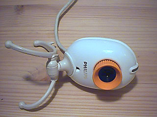
We start with the innocent little ToUcam 740 Pro...

...remove the lens and unscrew the only screw that's holding the housing together...

...remove two identical screws holding the board inside the case and
the PCB is free.
It's a good idea to leave the USB cable in place since the connector sits
very tight on the pins. Remember the position of the orientation-notch
in the CCD!
Operate under ESD save conditions !
Now we have to desolder the CCD. Protect it's surface with a piece of adhesive tape. Remove as much solder as possible from the pins with desoldering-wire. Then use a needle as a lever to gently lift the pins while heating them - they will snap of their pads with a little "click". If all pins are desoldered properly the CCD will fall of the board by itself. Don't force it!
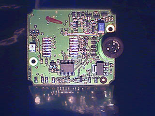
Clean the pads with desoldering-wire from solder. Examine the CCD location (pads, copper traces, vias, clearences, components) for mechanical damages and shorts with a loupe. The soldermask around the pads should be unscratched to prevent shorts. Measure the pads against their neighbours for shorts, measure all pads against GND (accessible around the mounting holes) to make sure no pad has been shorted against the surrounding GND copper fill (one pad of each pin row is connected to GND). It would be a waste to solder a fresh ICX098BL CCD onto a damaged board.
Handle the new CCD (and the old one of course) with care under ESD save conditions. CCDs are quite sensitive to electrostatic dischargements, so it's a good idea to wear a grounded wristband.
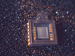
The new ICX098BL, the protective foil has been rotated 90° so that
the little handle get's out of the way for soldering.
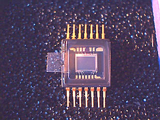
The pins have been bent for SMD soldering. Verify that the chip body
sits completely parallel to a flat surface and all pins touch the ground.
Now it's time to solder the CCD onto the board. Check first, that the
bent pins fit exactly onto the footprint on the PCB. Remember the position
of the orientation notch!
According to the CCDs datasheet the pins should be soldered with a 30W
soldering iron and each pin heated for max. 2 seconds. Let it cool down
and reheat when a solder joint hasn't been done correctly. Check all pins
for proper solder joints and shorts with a loupe or bino.
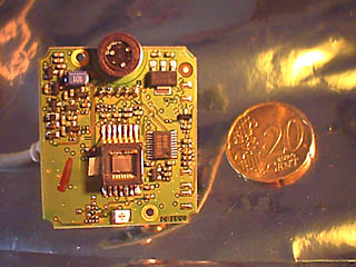
Finished ![]()
Remove the protection foil from the CCD top glass and screw the PCB back into the case. It's a good idea to do a quick functional test before closing the casing again.